If you are into IoT Security, exploitation or hacking, firmware analysis a very handy skill set to have. Here you will find out how and where to start including a video tutorial to guide you to start on firmware analysis with a firmware dump. The firmware I choose to use was the 25L12805F from WRTnode board.
WRTnode is a high performance CPU, low power consuming, cheap and small dev board that can run OpenWRT OS and also easy to port all open source software of Linux. OpenWRT is a Linux distribution for embedded devices, the framework to build an application without having to build a complete firmware around it; for users this means the ability for full customization, to use the device in ways never envisioned. Today, more and more devices could connect to internet, named Internet of Things. The WRTnode is a small node which could connect internet all by itself and do complicated tasks. Such as track a cat running over, identify what you are saying and twitter it, check email and pronounce for you, learn how your room layout and find garbage to sweep while streaming camera video to you over internet. Just to name a few.
To start you could use any device you may have at home that has a firmware or you can buy a cheap device like WRTnode so you can practice before opening up your Google Home, Alexa, Router, etc. You can buy it from here: WRTnode The first thing you should try to do is to identify the firmware from your board. Look at the descriptions on the top of the chips from the target board and google for datasheets using the code you found.

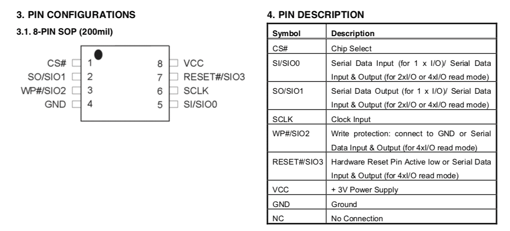
The picture above shows the firmware we had identified from the WRTnode. It is a SPI flash 25L12805F. Below is the pinout I found on a datasheet I downloaded from the Internet:
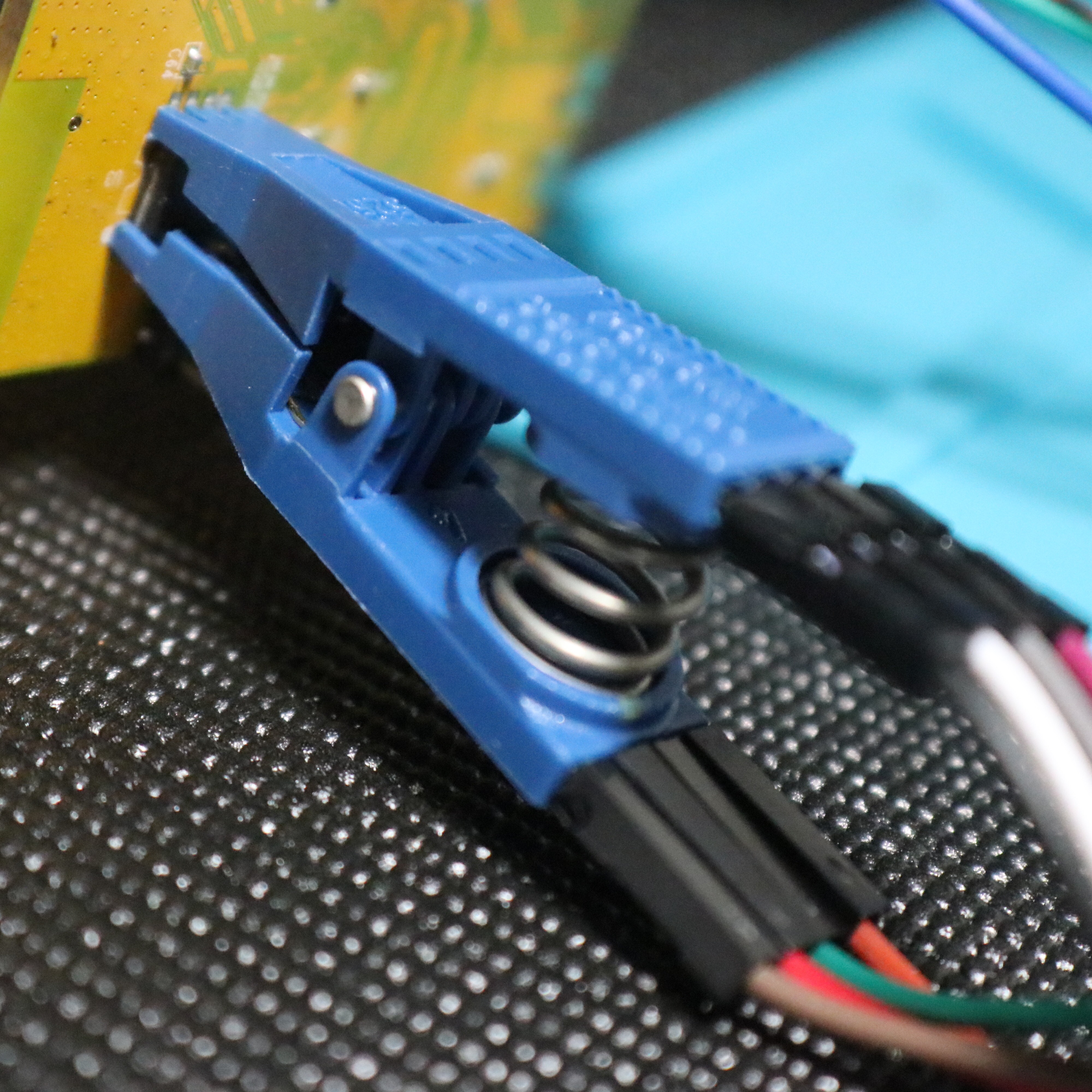
Now we can try to read the firmware from the chip. There are a few options like unsoldering the chip from the board and connecting it to a specialized EPROM read/write device, or attaching to a Protoboard. There are some people that prefer using hookclips to connect to the chip but I prefer using a SOIC8 clip. I find them very easy and handy. You connect in parallel over the chip on the board, not having to unsolder it.
 Now you need a hardware tool that can interact with at list a SPI interface. I used the Attify Badge as it’s very efficient and supports many interfaces like SPI, UART, JTAG, I2C, GPIO and others. But you could other devices like a more professional EPROM programmer, a Bus Pirate or even a Raspberry Pi.

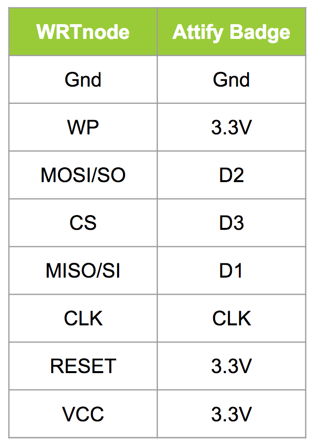
What you need now is to make the proper connections from the chip pins to the Attify badge, or the hardware you are using. The important is that you make the connections properly according to the diagram below:
 After making sure this is all good you can power up your hardware tool (in my case the Attify Badge). Don’t power up the WRTnode board. The power will be coming from the Attify Badge. Connect the Attify Badge to a Linux distro and confirm you can see it issuing the following command:
lsusb
For reading the firmware you will need a piece of software and we will be using a python program called spiflash. You can download it from here: https://github.com/devttys0/libmpsse/blob/master/src/examples/spiflash.py Go to the directory where you downloaded the spiflash and issue the following command:
sudo python spiflash.py -r wrt-firmware -s 20000000
You can use the help command to get more information but just for you know the -r is for reading the firmware and you could use -w to write the firmware to the SPI flash. The -s if for size and if you know the exact size of your firmware is good, if not just use a size that is large enough to read the entire firmware.
If everything went through you should have a file called wrt-firmware. Using binwalk extract the firmware so you can have access to the file system and make sure the dump was done properly.
binwalk -e wrt-firmware
Walk through the folders and files created. And that’s it! Check out the video below as well and don’t forget to register on my blog and YouTube channel clicking here.


